")
The legendary Tamiya 3 Speed chassis
Apart from the amazing Toyota 4x4 Pickup Hilux bodyshell, one of the most outstanding aspects of these chassis is the mechanical realism. Of course, the gearbox is the iconic part, but the chassis deserves attention too: just like the full-size model by Toyota, the replica made by Tamiya uses a ladder-frame chassis and leaf-spring suspension.
That's what we will now review as the chassis build starts with the partially assembled ladder-frame chassis:
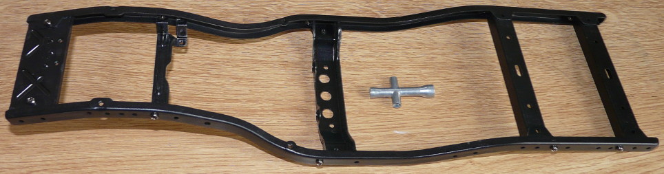
The iconic Tamiya tool is there to show the size of the part we will work on during the first 4 steps of the manual. Basically, we will focus on suspension mounts, leaf-spring mounts and rear bumper, along with the first element of the steering bellcrank. But the chassis is pre-assembled, meaning that only the minimum of screws to give shape were installed: many more screws will be required to strengthen the chassis.
Precisely, it is required to unscrew every screw Tamiya already pre-assembled in order to add thread lock to secure them. That's the beginning of the Loctite festival that will last almost all the build long: more or less, as soon as you put your hand on the screwdriver, you will need to apply thread lock somewhere. I mean, that is about 50 times during the first 4 steps of the manual.
A 3 Speed chassis, even in its re-released form like here, is a proud member of Tamiya's “metal age”, a wonderful era when Tamiya restrained their plastic injection know-how to the sole bodyshells (in RC). In concrete, there is a massive use of metal, as the weight of the models of the time prove, and the plethora of metal hardware doesn't help. As a matter of fact, only 3 plastic part trees are used for the whole chassis, the electronic boxes being the main parts.
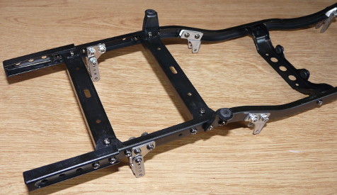
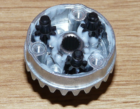
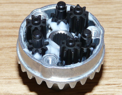
On the following photos shot after step 4 of the manual, only the white parts are made out of plastic:
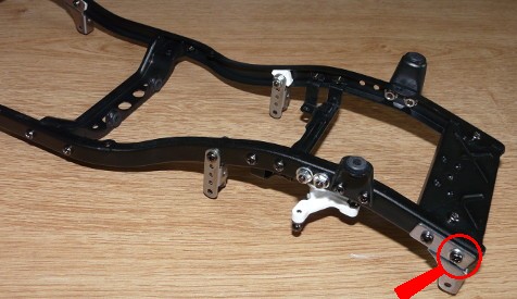
On the last photo, the magnifying glass points the one screw of the chassis that doesn't require thread lock as per the manual: yes, it is simply not listed as requiring thread lock. A detail? Nope, you will figure it out at the very end of the build process: in a few (many) hours, you will realize your mistake if you applied thread lock on this specific screw (and its twin on the other side of the chassis). Just in case, know that when a screw is secured with red thread lock, it tends to be not possible to unscrew it (this is actually what thread lock is meant for  ), especially when that screw is difficult to reach with standard tools. However, know that a cutting disk and a Dremel solve the problem by cutting the screw head so the rest of the screw can be removed once you reach step 38 of the manual. Well, guess how do I know that?
  .
.
Preparing the ladder frame chassis is finished for now. Now we go for the build of the axles, starting with the differentials and the bevel gears:
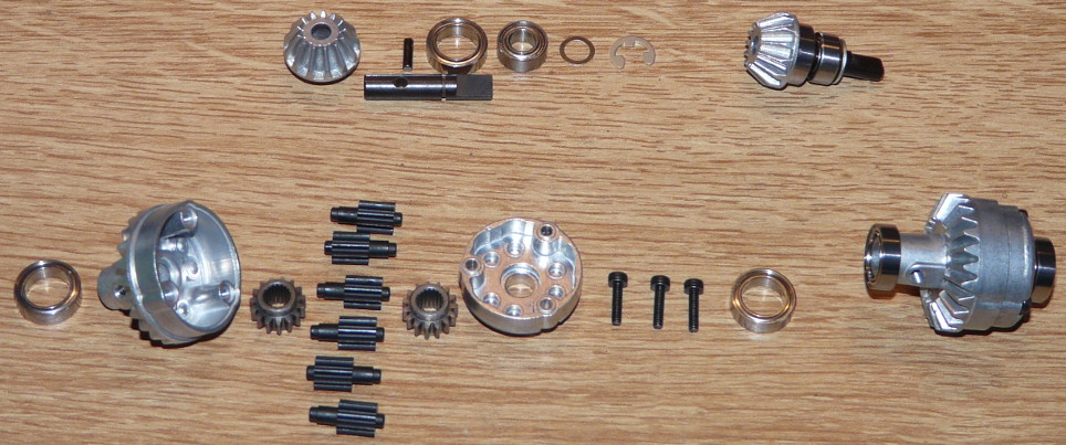
Everything has to be done twice because the differentials are the same for the front and the rear. Unlike with my LandFreeder / Mitsubishi Pajero I was generous with the grease (as recommended by the manual) despite both models running in the same conditions: at first, my CC-01 chassis was meant to take all trail abuse conditions, including the wet (if you see what I mean... ). Therefore, I first built it without grease in order to avoid dirt mixing with the grease and becoming some sort of abrasive paste that ruins gears within a few battery packs. After a few runs however, I soon realized that the CC-01 was never designed to take this kind of “submersible” abuse: protecting the gears is one thing, making it waterproof so that the model can be plunged is something else (impossible, actually). In fact, after a few runs, I generously applied grease on the gears of my Pajero for protection and gear smoothness. As of now, my model still runs into water, but not above the wheel nuts in order to preserve the whole gearing. This is why the gears in my Mountain Rider will receive grease, even more because of the complex 3 speed gearbox that I want to preserve as much as possible.
Now, let's place the front and rear differentials into their axles:
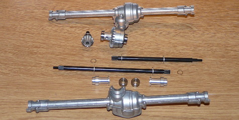
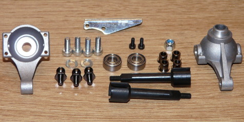
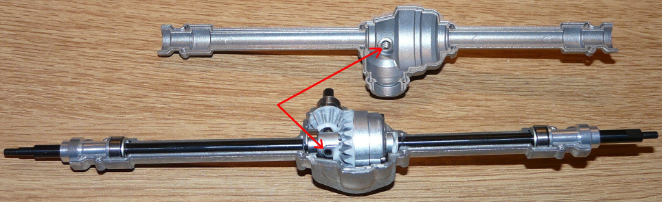
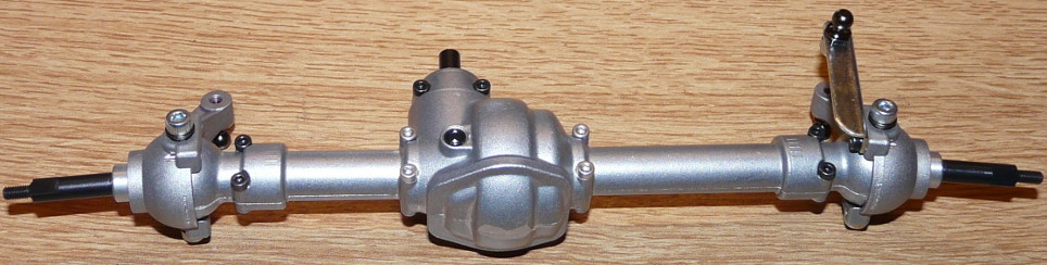
The front and rear axles are the same, except the front one is shorter because it later received the steering hubs. On the third photo, the arrows point the rear differential lock system, that is where you need to insert an axle. This axle goes through the differential casing and the wheel axle: as a result, the wheel axle becomes one with the differential casing, and the differential is therefore locked. The system is the same at the front: the screw pin (black) that you see on the casing (photo 4) hides the hole through which to insert the locking axle. This way, you can lock or unlock both the front and rear differentials even once the chassis is fully assembled. However, in practice, you will prefer to perform this operation while assembling the axles: it is possible to lock / unlock the differentials at any moment, but there is the easy way... and there is the other way.
At step 9, the manual recommends to file the ends of the front axle in order to smooth the knuckle arm rotation: on my model, they rotate perfectly smooth so I didn't have to file anything. May be the production process was improved since the writing of the manual.
At this moment of the build, 9 out of the 38 steps dedicated to the sole chassis have been performed. So far, I spent 3 hours to build this: I admit I took my time, but I believe it is important to say that this build is somewhat more complicated than usual models. Carefully studying each step of the assembly is required, both to prepare the required elements and the hardware (with thread lock), but also to carefully understand how some parts fit.