Assembling the Avante chassis: the gears
With Tamiya, you know the manual instructions are crystal clear. However, we are talking about the Avante here, probably one of the most complex model in RC history, a true piece of engineering demonstration: before to start the build, it is a good advice to first read the manual carefully.
Before the build, first open each screw bag and place the content in individual and identified boxes. In case the bag has no label, make one. You may wonder why, so take the time to click on the 2 next images to display them full size: the first one is a screen shot of the first two steps in the manual. The second is one of the last pages of the instruction manual.
First image: the 8 different screw types come for 3 different bags and from 1 of the 2 blister packs. Not mentioning the foam piece that come from another bag. Steps in the manual and bags do not match: you will spend your time picking in about every screw bag and blister pack at the same time. That's why I recommend to first open each bag and to store their content individually in labeled boxes before to start. Well, just an advice, you decide ![]() .
.
So, let's start the build:
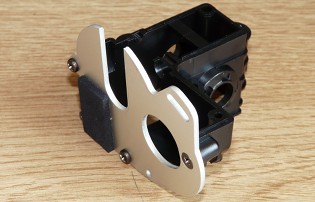
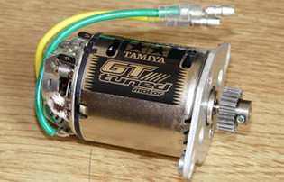
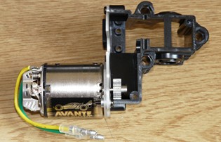
The starting point is the rear gearbox and motor mount assembly. As advised in the manual, the motor has to be placed so it leaves room for other elements further in the assembly process. About the motor, it is a special edition of an existing motor, namely the 53779 GT-Tuned 25T motor: for the Avante, it only features a specific sticker. And that's it. As for the 0.6 module motor pinion, it is a premiere in Tamiya's line-up of buggies in 1988 since all previous buggies were using 0.8 module motor pinions (and gears).
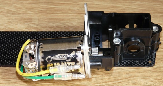
Installing the rear gearbox on the chassis: as advised in the manual, apply instant cement on the carbon chassis edges in order to protect it. The first thing to notice is the motor position: it is not horizontally mounted as usual, but will see this a bit further on. Next, let's build the front gearbox and insert the central driveshaft bevel gear:
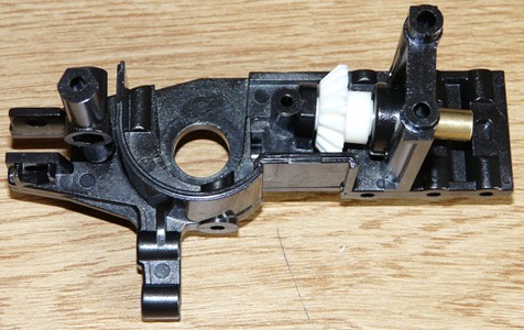
The front gearbox installed on the chassis. The bend you see behind the front gearbox is one of the battery pack stays:

Next, proceed to the front and rear differentials build:
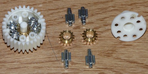
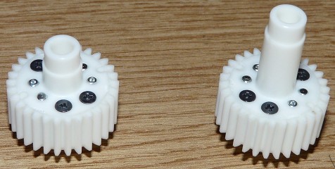
Both differentials are identical, except their cover. The bevel gears are straight and not conic as found on other models.
Then we place the ball bearings holding the differential before fitting the differential and the rear counter gear into the gearbox. Note the easy access to the differential for maintenance:
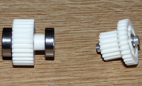
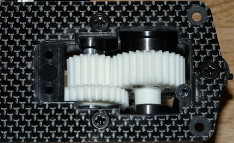
Repeat the same process at the front. The masking scotch piece you see is used to temporarily hold the bevel gear axle, as the manual recommends:
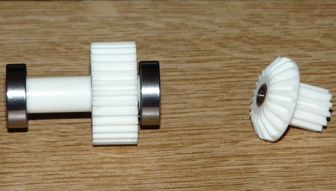
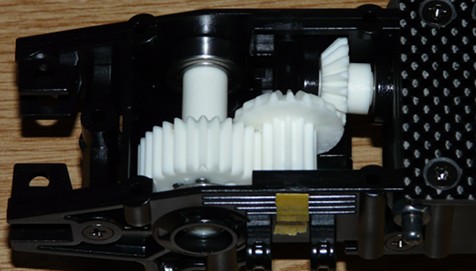
All these gears feel lightweight, lighter than gears found on other models in my collection. In addition, plastic parts, like the gearbox housings, also feel lighter than usual. But both gears and many plastic parts like housings seem charged with something that makes them stronger. You can feel it when cutting the parts from the trees: the blade feels like cutting graphite-charged material.
This is what we have done so far:

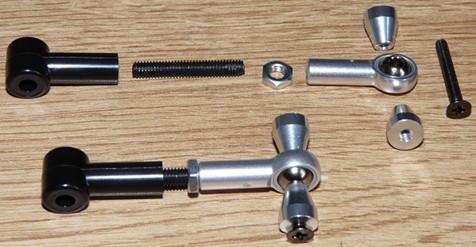
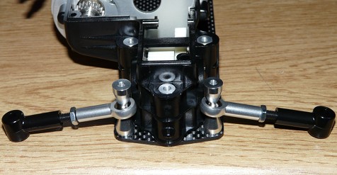
Now proceeding with the arms: on the Avante, arms are made of links and ball ends. The first photo shows an exploded view of one link and one complete link. The second photo shows them fitted onto the rear of the chassis:
The center ball differential, first in exploded view then assembled:
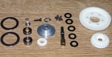
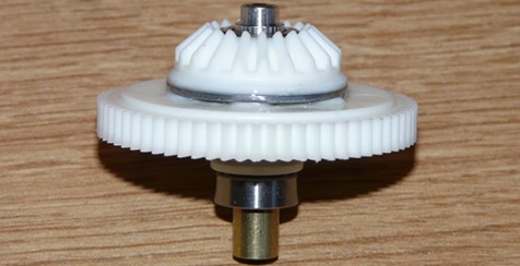
One note about the center ball differential: the manual warns not to over-tighten it and to use thread lock on the screw. You should follow the second advice, but the first warning seriously lacks precision. In fact, “do not over-tighten” is right, but you generally end by “under-tightening” making the differential to slip and absorb most of the motor power. Symptoms are a “whistling” differential and a car that lacks power at throttle (pretty much like a loose slipper clutch, actually). This is a know problem with the re-released Avante, but the original model suffered the same issue.
The solution: tighten the differential. Even if it is not easy to perform, tighten up to the moment when it is no longer possible to move the drive gear while you are strongly blocking the bevel gear with your hand (no tool!). At this point, both elements seem to be one because one can't move without the other one moving too. That is when your center differential is properly setup. Anyway, you should know this differential is not really made to be fine tuned depending on track conditions: either it is too loose or close to blocked. It is not meant to offer a wide variety of fine tuning setups as usual with classic ball differentials.
The center ball differential is located into the rear gearbox, which offers these interesting views of the chassis:
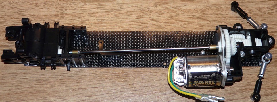

This is not a visual illusion: the central driveshaft literally heads down to the front gearbox. The reason for this is to lower the center of gravity at the front of the chassis. At the rear, it can't be lowered due to the spur gear size. This explains why the driveshaft is not horizontal, and as a consequence, it explains why the motor is not horizontally mounted either. The motor has to respect the same angle as the spur gear, the spur gear respecting the central driveshaft angle between the front and rear gearboxes.


