The Renault 5 Turbo tires
Here's the condition of the tires on the model I received:
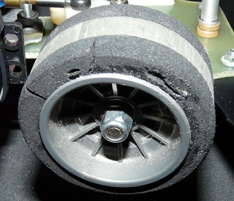
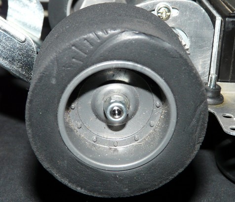
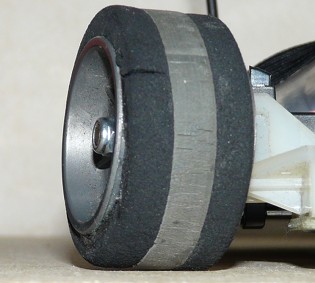
Front and rear, despite the foams showing their age, the tires should still work correctly if not exaggeratedly demanded on. The front tires are specific since they feature two kind of compounds: the center grey band is hard compound whereas the interior and exterior sides are soft compound. In straight line, the tire mainly drives on the center hard compound band that provides low grip: not a problem since the car doesn't need it. The benefit is a reduced tire wear. However, as soon as the wheels turn, the front tires drive onto the soft compound side, offering more grip, thus making the front drivetrain more precise in corners. In short, these famous "diplos" supply an on-demand grip depending on the chassis needs. Enough words, images:
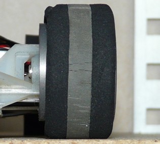
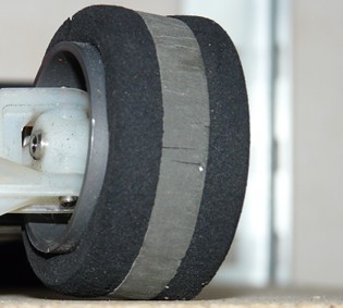
1st photo: the car goes in straight line, the tire mainly drives on the hard compound center band.
2nd photo: the car turns left. The front right tire mainly drives onto the interior soft compound band.
3rd photo: the car is still turning left. The front left tire mainly drives onto the exterior soft compound band.
The variation of the wheel camber angle in corners is due to the caster angle, one of the settings involved into suspension geometry (see the definition on Wikipedia). Here, this makes use of the "diplo" tires characteristics by providing an angle to the wheels. By doing so, the surface with more grip is forced to be in contact with the ground when the car turns. The goal is to optimize the front drivetrain grip in order to reduce understeer.
Useful tip: you can mount foam tires from the new RM-01 chassis onto the Renault 5 Turbo rims. Despite sharing the same interior diameter dimensions (which allows to mount them on the rims), the RM-01 rear tire exterior diameter is a little bit smaller than the Renault's and the RM-01 front exterior diameter is a little bit bigger. So this is not a 100% compatibility, but this is a "mechanical" solution for driving safely. For the RM-01 tires, references are 51483 and 51484 for stock tires, or 54334 and 54335 for Hi-Grip versions.
The servo-saver
That is another interesting aspect of this chassis:
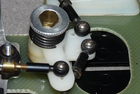
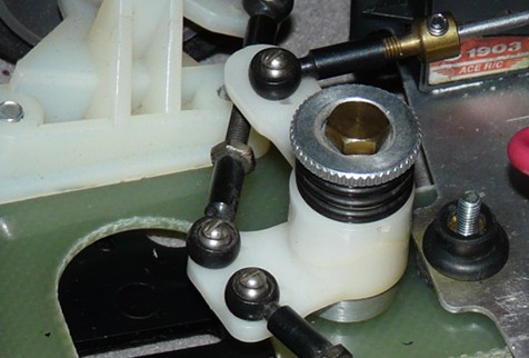
Some sources claim it is the same servo-saver as the Racing Master mk1's chassis: wrong, even though the design is close. Despite being a quite advanced servo-saver design comparing to standard systems used so far by Tamiya (or even compared to basic modern units), this design was very well known and widely used by other manufactures, especially since the late 70's in the 1/12th pan-car category.
The system is made of two nylon beveled parts mounted straight that are held by a spring and a nut allowing to tune the stiffness of the mechanism. With adjustable turnbuckles, this complete system reveals to be solid and very precise.
The Renault 5 Turbo gearbox
Now, let's go to the chassis rear of the chassis:
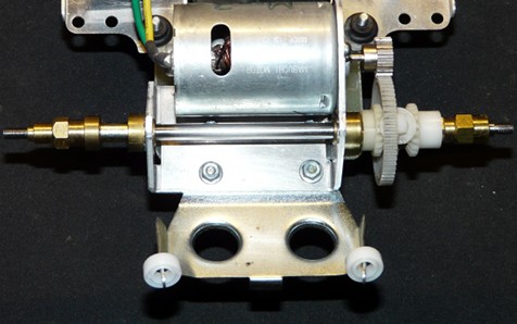
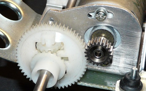
The propeller axle was already seen on older Formula 1 chassis from Tamiya, the same applies to the bevel gear differential that could be found on the Ferrari 312T3 for example. The Mabuchi 540 motor mount can accept 0.6 pitch motor pinions from 15T to 20T, despite the manual only recommending either 15 or 20T. As usual, I used the biggest motor pinion to preserve the gears, even if I will probably need to limit the Mabuchi power through radio settings: I suspect this chassis to be at least as fast as my Ferrari 312T3.
For those of you wondering about the two 1150 plastic bearings on the rear body mounts: they serve as protection once the lexan bodyshell is installed ![]() .
.
Electronics and finishing the chassis
So now, let's get to the most complicated aspect about this chassis: fitting the electronics, but above all, finding how to properly cable-tie everything.
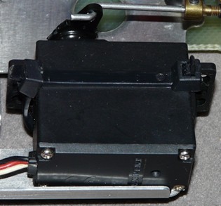
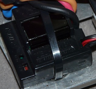
First operation, securing the steering servo stay. As per the manual, it needs to be double-sided tapped onto the electronic deck: as per my experience, this is the best way to loose any steering control over your car. In addition to the double-sided tape, I used nylon collars passed through existing holes in the electronic deck. I applied the same treatment to the TEU-101BK electronic speed controller.
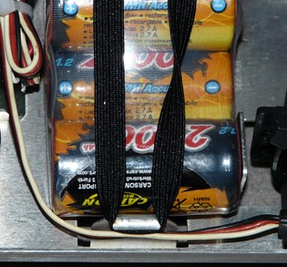
As for the battery pack, modern 6 element nimh packs can't fit on the electronic deck, thus the use of a "hump back" pack. An elastic band secures it, just the same as the period method. The receiver was meant to go alongside the TEU-101BK: because I couldn't find how to properly pass cables, I decided to move it backwards where the servo operating the mechanical speed controller was originally located. Another solution would have been to place it at the very rear end of the chassis, behind the motor: this was the place meant for placing the receiver battery box. Because my chassis came without the original mechanical speed controller that would be located above the motor, I didn't have this "bridge" over the motor to pass cables anymore.
Overview of the chassis ready to run:
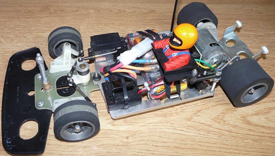
Sorting cables didn't give a perfect result, but it works and all components are correctly fitted. Overall, this chassis design is simple, not to say basic. But my instinct tells me it will be pretty fast and handling well on the track.
You can also notice the 850 bronze bearings used as spacers at the front body mount: in stock form, there is a plastic part used as a base for the body mount in order to reach the correct height for the bodyshell. As this part was missing on my chassis, I picked up these replacements from my hardware.
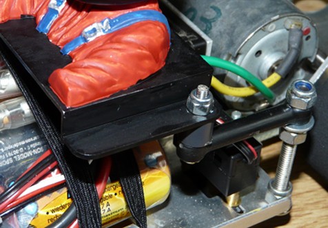
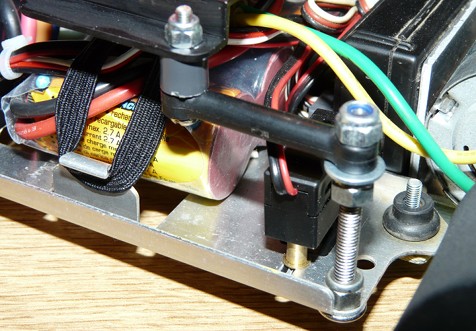
Above, you can see the spacers I used to make the switch higher so the button is not too prominent under the chassis plate. Photos also reveal the system I made to fix the driver: on the stock model, the driver plate is fixed onto the servo operating the mechanical speed controller from the place where I installed my receiver. The most observants of you will notice this is not the original driver but a Grasshopper II or a Hornet driver.


