Le châssis de la Porsche 959
As I said before, it was built from new parts by a person who sold it. Then I did buy it to a Vintage-RC forum member who didn't change anything to it. Visually, the chassis looked perfectly built, except the big problem at the front left lower arm and missing parts like the antenna post and the servo link. But the chassis soon revealed some bad surprises after a closer look.
Repairing a front arm
Plastics are so fragile on this chassis that you'd better pre-drill holes before screwing, especially on the front and rear arms. But, pre-drilling a 3mm hole to screw a 3mm screw is obviously stupid: but this is the problem I found on the front left lower arm to screw the damper ball connector. So I tried to remedy this built mistake: good news, I found a working solution that may interest owners of this chassis because this problem seems quite common.
The idea is this:
- refill the hole
- pre-drill using a 2.5mm drill
- use a reinforcement system
- screw the ball connector
For the first step, I used a product from Pattex called "Ni clou ni vis" ("No nail no screw": sorry, can't find what's this product name abroad): it is a very resistant glue being specifically hard once dry and that doesn't alter plastics or make them fragile (the opposite of cyano glue for example). So first, fill the hole with it, completely stuff it with the paste. Don't worry if if you spread glue around the hole: once dry, you can easily sand it or even paint it. It is said to be dry within 48h but I noticed the paste gets totally hard after 96h.
Second step: drill a 2.5mm hole in the cement. Nothing difficult here, you just need to care about drilling straight and not to deep. Make a mark on the drill with the corresponding ball connector screw length.
The third step is mandatory, otherwise you'll crack the plastic. Indeed, the cement hole is 2.5mm diameter but the ball connector screw thread is 3mm diameter. This means there is too much material inside the hole: under the ball connector pressure, the cement will force on the fragile plastic and crack it.
Reinforcing means to apply an outside constraint force in order to avoid the plastic to crack. For this, I used a U-shape spring mount that you find in many kits. This U-shape part will enclose the ball connector screw thread.
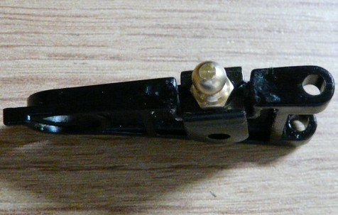
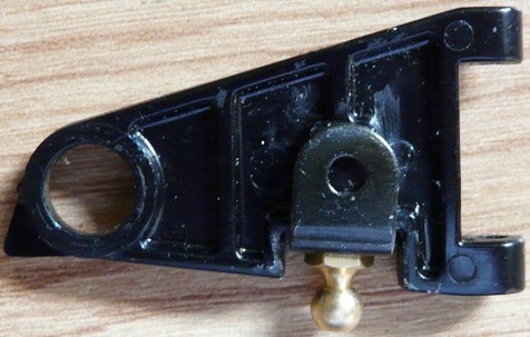
The U-shape dimensions are not perfect for this, but this is the best candidate I found in my spare part stock. You need to fully insert it on the arm and then foil the sides.
Last step is screwing the ball connector: because of the plastic being so fragile, I recommend you firmly maintain the U-shape part with pliers while you screw the ball connector. Be sure to screw progressively in order to recreate the thread into the cement. The final result is solid and somewhat discreet even if it is not beautiful: once the arm back onto the chassis, everything seems fine but I can't guarantee that it will be able to bear strong constraints. Note that this repair may not suit the Toyota Celica Gr.B because of the sway bar stay.
Custom changes
When you miss necessary parts to finish a chassis, there are just two solutions: either you already have them or buy them, or you use other parts that will do the same. Parts for this chassis being so rare and expensive, I chose the second option.
Custom servo mount
Custom battery door
Custom inner bumper stay
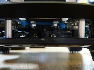
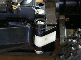
The steering servo needs a specific part to be mounted and I couldn't find anything close to it in my spare part stock. I just used a servo horn fixed onto the chassis using a longer screw.
The battery door part is the one I found on the chassis when I got it: the problem is that it doesn't belong to this chassis and it is too high to leave room for the steering link. So I just savagely butchered it to keep using it but making it much lower so the steering link has enough clearance.
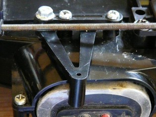
The inner bumper stays are the two vertical aluminum parts: they come from the mounting set of TG-10 urethane bumper I had left from my Ford Focus RS WRC 2001. The Rilsan collars you can see at the top are there for something completely different we'll see later on.
Cable tying
Whatever the model, I just hate doing it: first because this is not the most interesting part when building a model, but most of all, this step comes when you know that everything works on your chassis and you just want to go test drive it.
On this model, arranging cables is very difficult to do both because there is not much room for that and because the chassis layout doesn't help to separate radio cables from power cables.
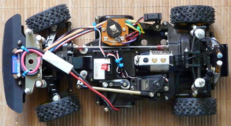
In concrete here's the chassis layout:
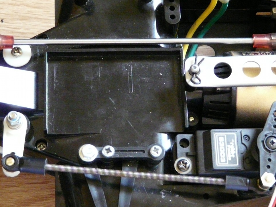
From the top of the photo, the empty space on the right is meant for placing the mechanical speed controller servo (that goes in front of the servo, right in the top center of the photo). The mechanical speed controller is replaced by a TEU-302BK, thus the empty space. The central drive shaft (always difficult to deal with if you don't want cables to get into it) make a separation line with the main electronics platform and the 540VZ Technigold motor. The steering servo and its link make another separation line on the lower part of the photo, keeping the battery plug wires apart from the rest of the chassis. Last detail: the antenna post is located on the right side, above the motor head (not shown on the photo).
To make it clear, the electronic components (speed controller and receiver) and all the cables have to fit onto the central platform that is big enough to place everything. In straight words, you can't arrange cables properly this way, especially because you must keep things low to allow enough clearance for the pilots cockpit set.
I tortured my mind, tried and tested different approaches and found no correct result: either the electronic components go onto the platform and you pile up the wire like spaghetti on top, or cables need to get over the central driveshaft and the steering link and you to pray wires don't touch them.
Finally, I decided to get back to the original basics: the receiver goes on the central platform. The speed controller is originally mounted in front of its servo... and its resistor goes onto the front bumper. This is that last mounting step that gave me an idea.
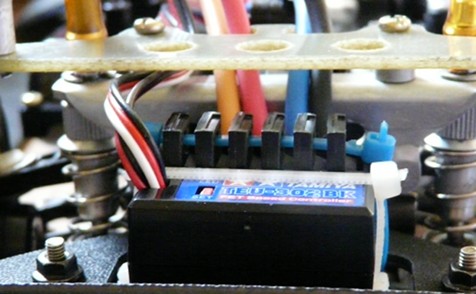
ESC installed
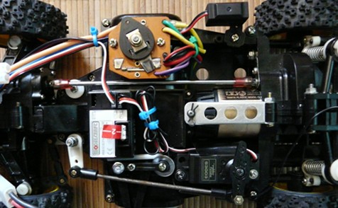
Cable tied chassis
The Rilsan collars seen on the inner bumper stays are those used to fix the electronic speed controller. As said before, this place is originally meant for the mechanical speed controller resistor: this is where I got the idea. To some extend, this is a kind of wink to the original setup ![]() .
.
The TEU-302BK speed controller is fixed using Rilsan collars on the ceramic resistor plate. There are two main interests in placing it at the chassis front:
- you can benefit from the cable length without having to wind them
- you reach the motor wire and the battery plug avoiding the two moving axles (central driveshaft and steering link)
To keep cables apart from the central driveshaft, I chose to mount the mechanical speed controller where it was originally meant to go. Of course, I deactivated it and it provides anchor for the cables and gives a Vintage touch to the chassis. This frees all the room on the central platform for the receiver and to cable tie the antenna and steering servo wires extra length. The antenna wire just goes to the front of the steering servo and then on the chassis side to the antenna post at the rear. I used small portions of antenna tube to drive the wire where I wanted.
After hours spent thinking about how to arrange cables on this chassis, the solution was to keep humble and not to try to improve what Tamiya already designed.
Chassis overview
Profile view
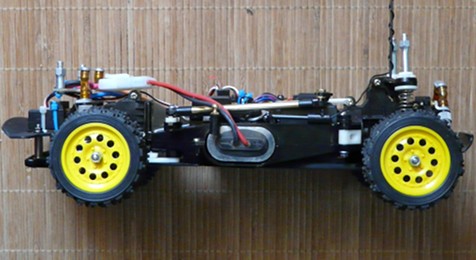
The chassis is now complete and fully operational: it still needs to be covered by its beautiful bodyset before I can go to the track and make it run.


