Building the Wild One chassis
Tamiya makes efforts to provide explicit manuals that drive you through a natural assembly process: so no need to improvise, let's follow the guide. The first steps are dedicated to the front drivetrain before assembling it to the chassis:
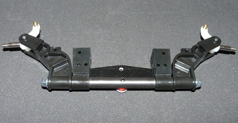
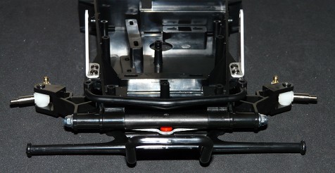
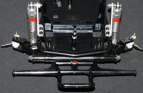
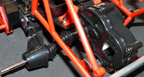
On the first photo, I removed the front bumper to better show the drivetrain mechanics: this is a trailing arms suspension. The front axis is used as a pivot for the arms on which the uprights are fixed. The two holders at the center will be screwed to the bathtub chassis, all this being reinforced by a black epoxy plate underneath. The second photo shows the drivetrain assembled to the chassis (bumper is fitted back) and the metal suspension mounts for the dampers.
Talking about dampers, that's the moment to mount them. Tamiya intentionally separated front dampers from rear, both in bags and steps in the manual. This is because front and rear dampers are different, but above all, because they need different oil viscosity: this is the first model I notice this.
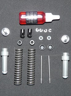
The first photo is a rapid inventory of the main parts needed: keeping it short, you can notice the red oil bottle (yellow will be used at front) and the 3-hole pistons (softest setup). Apart from a pile of small parts in the lower tank cap (Tamiya will make this simpler later on), these are the precursors of the CVA dampers still used in modern kits.
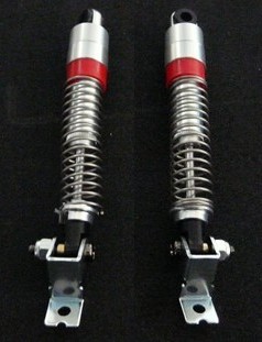
The second photo shows the assembled dampers mounted on their brackets: you can notice the springs are so soft they don't keep aligned. This is also because the spring is a little too big for the tank cylinder diameter and more obviously for its lower stay. The last photo shows the dampers mounted on the arms: as you could expect, they are very soft.
This part being done, we now go for the assembly of different parts at the rear of the chassis and the rollcage assembly:
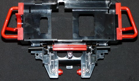
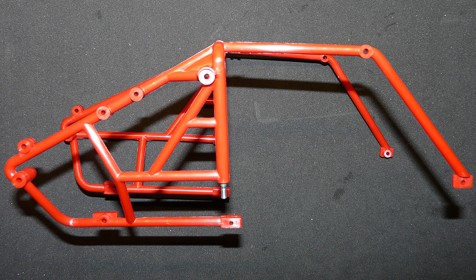
The first photo shows the red parts for this step of the assembly: on the sides, the battery stoppers. At the bottom (rear of the chassis), parts that will hold the gearbox. On the second photo, the easy to assemble rollcage: two parts ("sides") held by a metallic tube (hidden on this photo).
Here we are so far:
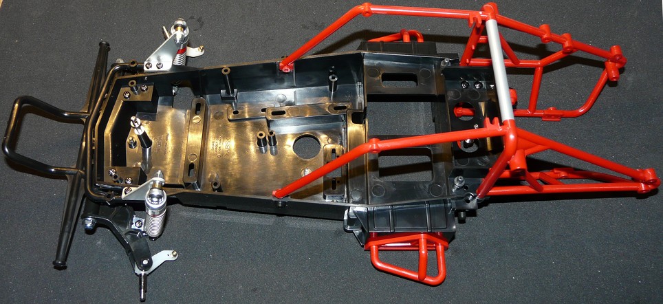
At this moment of the assembly, step 12 is completed (over 41), Bag A is now empty and several parts were already taken from the different part trees. I recommend you pay attention on how to mount the rear mount posts at step 12: see below in the "Final assembly" section for more details.
It is now time to start assembling the gearbox made of two plastic housings, a planetary differential and the necessary ball bearings. About these, a sticker added on the box proudly claims "Bonus parts included": it refers to the bearings. However, only 8 type 1150 bearings are included: 2 type 1150 and 3 type 850 for the gearbox are missing.
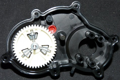
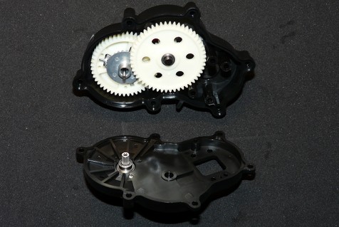
Once the gearbox is assembled and fitted to the chassis:
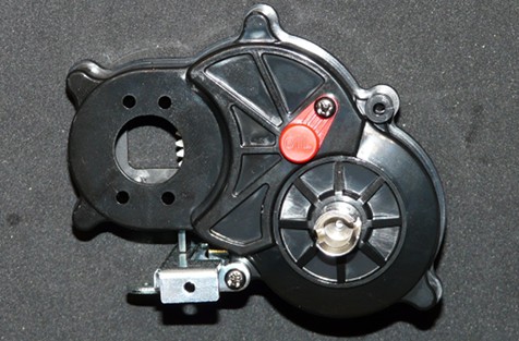
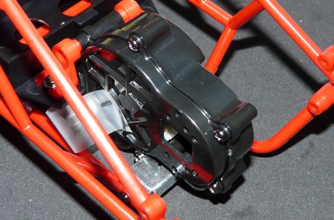
You can notice the differential gearbox joints are designed for modern drive shafts instead of hex dogbones on the original version. This same improvement was brought to the Frog re-release. You can also notice the metallic stand for the gearbox that will help reducing constraints due to the transmission cantilever and the scotch tape temporarily maintaining the gearbox joints (as recommended in the manual).
After installing the drive shafts into their protective joint boots, the trailing arms and the motor:
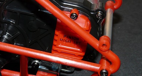
Little decorative touch on the second photo: I simply used a black pencil to draw the letters on the red part that closes the gearbox. The motor is the stock Mabuchi 540 found in the box: I see no interest in mounting a better motor on this model. As for the motor pinion, I chose the 18T as the marking shows, but the 15T is also available (both are in the box). It is not for top speed: on this kind of model, I generally prefer to use a long gear ratio in order to reduce stress on the gearbox at launch. Since you can limit the top speed thanks to the radio setup, you can easily get a smoother model to drive.
End of the rear drivetrain assembly after mounting the dampers:
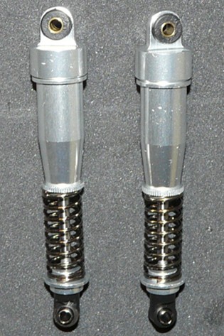
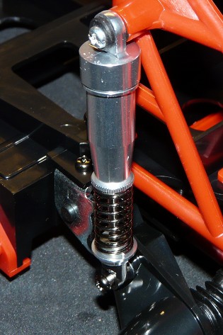
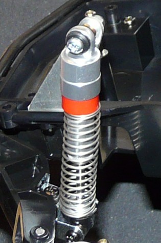
The third photo is a reminder of the front dampers: you can immediately see the rear drivetrain will offer much less suspension travel than the front. In addition, suspension is much harder: this is due to the combined effect of a more viscous oil (the yellow one), harder springs and the 2 hole piston instead of the front 3 holes. Obviously, smoothness and suspension travel were limited both to preserve the gearbox from hitting the ground when landing jumps, and because the drive shafts can't cope with great length variations. On the contrary, most of the weight being concentrated at the rear of the chassis to improve traction, the great front suspension travel and softness should allow the front drivetrain to stay in contact with the ground to steer the buggy.
New step: electronics. Quite an easy job since the chassis leaves plenty of room to install everything you need:
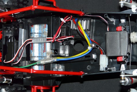
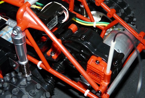
Unlike the manual recommendation, I chose to install the receiver right in front of the gearbox (where the receiver batteries used to go). But then, access to the receiver becomes compromised since you will have to remove the roof, the driver cockpit and part of the rollcage. This is only for aesthetics: it lets you drive the antenna wire to the rear of the chassis and to mount it on the rollcage. When placing the receiver into the chassis tub as recommended in the manual, the antenna wire needs to be cable-tied to the rollcage around the driver cockpit.
One word about the new TEU-105BK electronic speed controller: it is the same as the 104BK, except it now has a BEC circuit (at last!) and a metallic heat spreader. To set it up, the procedure is as simple as the 101BK's because it is the same.
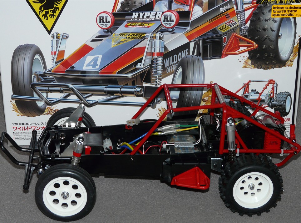
The chassis is now complete and ready to go: the final result is shown on the photo below. However, please note that I completed the assembly just for the photo: the horizontal bar at the front of the roof as well as the front rollcage pillars should be screwed only after you have mounted the driver cockpit.
So now it is time to go for the bodyshell...


