The Tyrrell P34 Six Wheeler motor and gearbox
The motor is that devilish Mabuchi RS-380 stuffed with steroids. Here's a comparison table with the standard 540 motors: the SH version was made by Mabuchi and can be found on almost any Tamiya model until the 90's when it was replaced by Johnson Electric J version we still can find in most modern kits. Please note values are theoretical and given for 7.2V:
| RS-380SH | RS-540SH | RS-540J | |
| Revolutions/minute | 13 000 | 12 500 | 14 500 |
| Torque (g-cm) | 75 | 200 | 255 |
| Current drain at load (A) | 2.8 | 6.5 | 7.9 |
At first sight, the RS-380 rpm value seems correct... except that with so few torque compared to the 540, the RS-380 will struggle to move the car and reach its maximum rpm. Especially since the Tyrrell P34 weights a "ton" (1.4 Kg) with its 6 wheels, its aluminum chassis and its heavy ABS bodyshell. A standard 540 motor gives wings to my Footwork FA13 (1,1 Kg), but I guess the Tyrrell will be much more reasonable... The manual says it all: 26 km/h top speed with 6V cells. With 7.2V cells, the top speed should reach 30 km/h: we'll see that at the first run.
There is an optional 540 type motor mount but I prefer to first test with the original setup. If the car reveals to be too slow, then I'll do my best to find one if it is still available somewhere: anyway, I don't want to make this model fly.
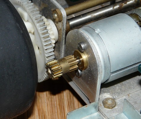
The standard gearing let's you choose between 4 setups: two short ratios (19.4 and 23.3) and two long ratios (5.8 and 7.0). The long ratios can be setup by positioning the motor directly onto the spur gear whereas the short ratios require an additional intermediate gear as shown below:
Long ratio setup (high top speed)
Short ratio setup (high torque)
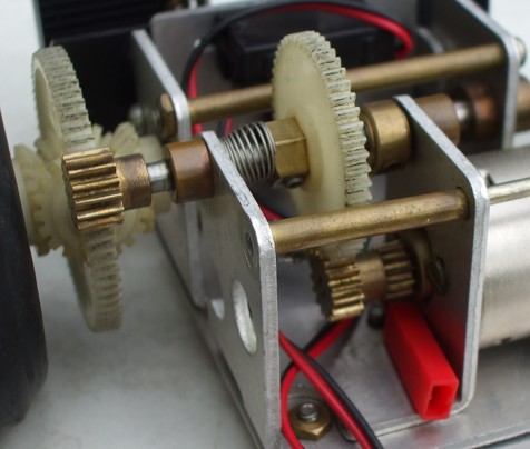
In addition, ratios can vary by inverting the motor pinion position: on the first photo, this is the longest available ratio and the second photo the longest of the short ratios.
The photos also show the planetary differential gear mounted on the rear right wheel: simple and reliable design, this is the ball-differential ancestor that can still be found at the very same place on modern Formula 1 chassis from model 58084 released back in 1990 (some 13 years later).
The very first test run in the loft corridor led to a dramatic conclusion: the steroid-stuffed RS-380 motor can't decently move the 1400 g weight car. The lack of torque is obvious: rear tires will never burn... even on ice ![]() . Once in motion, the top speed is so incredible that any of my other car can go much faster in reverse. Hoping this was only due to the longest gear ratio, I reverted the motor pinion to go for the shortest I can set on the car (since I don't have the intermediate gear): the car starts much fast... at start. Unfortunately, performances are low, not to say ridiculous: any straight line longer than 10 meters will make any driver have a nap until the car reaches at least the break point for the next corner.
. Once in motion, the top speed is so incredible that any of my other car can go much faster in reverse. Hoping this was only due to the longest gear ratio, I reverted the motor pinion to go for the shortest I can set on the car (since I don't have the intermediate gear): the car starts much fast... at start. Unfortunately, performances are low, not to say ridiculous: any straight line longer than 10 meters will make any driver have a nap until the car reaches at least the break point for the next corner.
Conclusion is easy: either my motor is almost dead or it has no power enough to decently run this car. Solution is easy too: either I look for a compatible motor with more torque and top speed or I have to find the optional RS-540 motor mount.
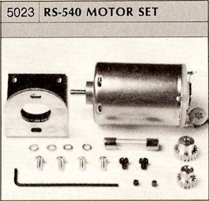
I chose to go for the period SP-5023 hop-up that features the motor mount, the RS-540 motor, motor pinions and a fuse for the mechanical speed controller.
Option SP-5023
Once installed in the chassis
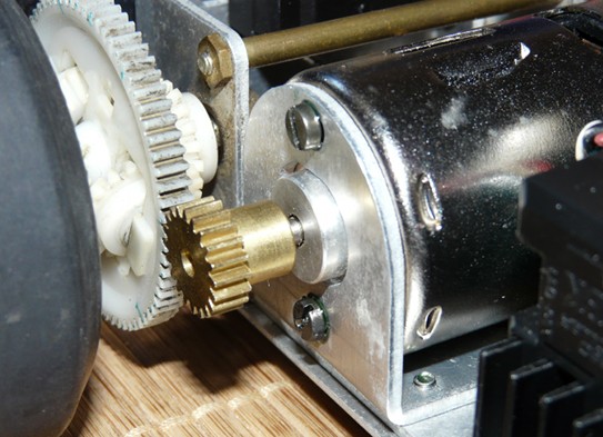
With this new motor mount, I now have two new gear ratios available: 18.64 with the 15T pinion and 13.98 with the 20T pinion. I chose the longest gear ratio for a better top speed in order to see how the chassis performs. But this is also meant to reduce the available power at low speed since I guess this car might behave with a true "vintage touch" that I'll need to cope with if I don't want to risk dangerous stunts on the track.
The radio deck
This is the part of the chassis that hosts all the electronic components: the steering servo, throttle servo with its mechanical speed controller featuring a fuse, the battery holder, the receiver and the cells pack. This chassis was designed to accept all three different propulsion pack types from the time, each one delivering 6V:
- 4 dry cells
- 4 NiCad cells
- 1 1200maH pack of 5 elements
The manual states that duration of run is about 50 minutes thanks to the low powered Mabuchi RS-380.
Even if I have everything to leave my Tyrrell P34 as per its original electronic setup, I will give it modern components not to risk any control loss when batteries go low. A new TEU-104BK speed controller will be enough to drive the Mabuchi 540 mpotor. For the batttery pack, the stick shape modern format is a bit too long to fit under the bodyshell: I could have modified a battery pack like I did for my Celica LB Turbo but I don't have any more left to sacrifice for this model.
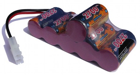
So I am going to use a modern "hump pack" that Carson had the great idea to release since the Rough Rider and Sand Scorcher were re-released. But my Tyrrell P34 from 1977 was never designed to host it so this will require some chassis modifications. I started with a basic idea: simply put the hump-pack on the radio deck. Unfortunately, it is a few millimeters too high to perfectly fit under the driver cockpit.
The Hump pack battery
Fitted on the radio deck
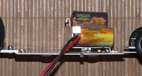
It is only a few millimeters too high, but the bodyshell lies on it and I don't like the idea that this will put constraints on the bodyshell holders. Several options to solve this:
- to relocate everything and to fit a modern battery pack longitudinally
- to relocate the battery pack behind the deck (where the receiver and speed controller are)
- to remove the deck and fit the battery pack right onto the chassis
- to mod the deck
I didn't chose to radically change the chassis setup since I wanted to stay as close as possible to the original. Same choice about relocated the battery pack at the rear of the chassis: this would also seriously modify the weight distribution to the rear of the chassis that already suffers from understeer.
Remaining options were to remove the deck (but then how do I fix the battery pack?) to modify the deck. I went for that last solution which idea is to lower the deck by folding the mounts in order to stick it to the chassis plate. The height clearance is enough and the deck can still be hold by the two remaining holders. For the two unused holders, you can either drill the chassis for new mounting points or stick the deck with double sided tape. I chose the last solution.
Electronics from speed controller side
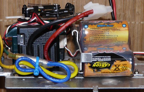
Electronics from receiver side
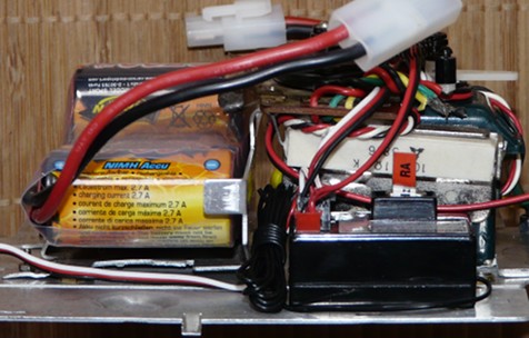
For the rest of electronic setup, the antenna post is located on the left of the bodyshell: no need to wonder where to place the receiver and the speed controller logically goes the other side leaving room in between. It is now rare to have so much room on modern models so I decided to mount the original mechanical speed controller and throttle servo for the "vintage touch". Of course, they are not connected.


