")
The leaf spring suspension
The suspension system is undoubtedly interesting (it is the same as the one used by Toyota's full-size car) and the build is undoubtedly too one of those pure moments in RC assembly. I'm talking about raw, genuine, authentic vintage RC, when one unique assembly step can fill one full page of the manual. I'm talking about step #10 in the manual, one remarkable marathon step that can be summarized with only 2 photos, no need for more. And honestly, when you are in the middle of that #10 step of the manual, you just don't want to touch the camera  .
.
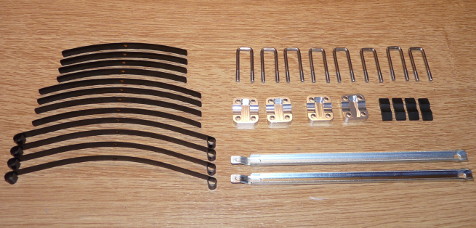
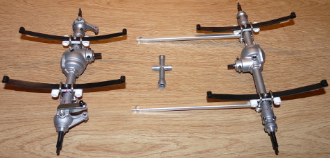
I confess I didn't shoot the screws and some additional parts required to complete the assembly of the leaf springs on the axles. But really, that's just a meaningless detail. The first photo is a break-down of the leaf-springs: there are 4 sets of different length leaf-springs, 2 radius arms, U-shaped bolts and parts to maintain the leaf-springs. The second photo shows the final result... 3 hours later. That's what I meant when I wrote "marathon step": 3 hours  .
.
What photos can't depict is how difficult it is to properly assemble the whole thing on the axles. Not only do you need to assemble them, meaning to build them so they hold together, but you also need to precisely set them up in the same process. That is because the placement of the leaf-springs on the axles requires to be extremely precise since their exact position determines the anti-dive angle of the drivetrain, that is 0° at the rear and +5° at the front (more about anti-dive in the article about my Dyna Storm).
The red marks you see on the axles and the leaf-spring white holders are meant to help align the leaf-springs and the axles following markers Tamiya engraved on the parts. I you ever build or re-build a chassis like this, I do recommend you use some marking method to help you align things . Among other recommendations for this #10 step of the manual, take your time to exhaustively study the steps to follow. Again. And again. Once more. Precisely identify the direction of each part in the build because some parts wear markers to help you, and these markers require to be respected to perform the build: be careful, you will probably not notice these markers at first sight, and you may not notice their representation on the manual drawings either at first sight. As for the not supplied in the kit “synthetic rubber cement” the manual recommends to use, either you already have it or you can use whatever glue as long as it is not suited for plastic and metal. Precisely, glue that will not glue because it is not made to glue plastic or metal: the fact is that this glue will only serve to temporarily hold the parts together to ease the build, but it should not secure the parts. In concrete, forget CA glue or bi-component glue: that liquid U-HU will be perfect, this one glue we all used at elementary school to stick whatever “masterpiece” we made to proudly bring back home at the end of the day.
Not much left to say about this #10 step: take your time to very carefully read and understand how all parts need to fit together. The build is not easy, but I think I already gave my best recommendations to get through it. I guess you will have to experiment it by yourself to enjoy it... afterwards .
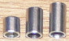 Before talking about assembling the axles on the chassis, one advice: it is very important to precisely identify all the parts in a bag before starting to use them. At this moment of the build for example, we open the bag B we will start using at step 11. Among other parts, there aluminum “tubes” called spacers in the manual. So far so good, except that there are not 2 different kinds of “tubes” as you may first think, but 3 of them: there are reference BA17 (7.5mm), BB10 (6.5mm) and BB11 (4mm). Double-check them before you start step 11, especially BA17 and BB10. Trust me .
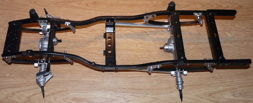
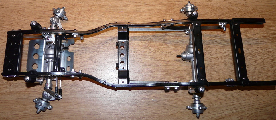
At this moment of the build, the whole chassis layout can be admired, offering the sight of an amazing mechanical solution, looking scale realistic and identical to the full-size RN36 version of Toyota's Hilux. Well, I wrote “looking” because I am no mechanic and I never owned the full-size Hilux to compare: by “scale realistic” and “identical”, I describe the feeling to see something that definitely looks like the real thing, at the very least like something that “could work in real”.
The hydraulic suspension
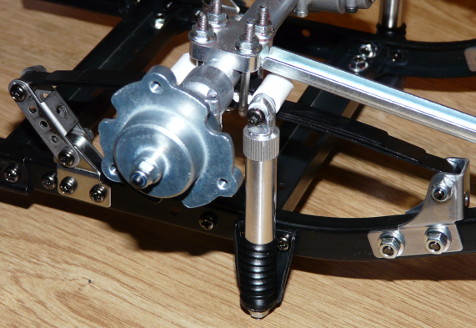
In addition to the leaf-spring suspension system, Tamiya's 3 Speed chassis is equipped with hydraulic dampers that work very much like the original Wild One's. Instead of using an oil seal, theses dampers work with a free damper rod and a pressure spring in the damper cap. Distinctive aspects: they do not use external springs, they are installed upside down and they are equipped with a rubber boot to protect the piston rod.
Here they are are different steps of their assembly:
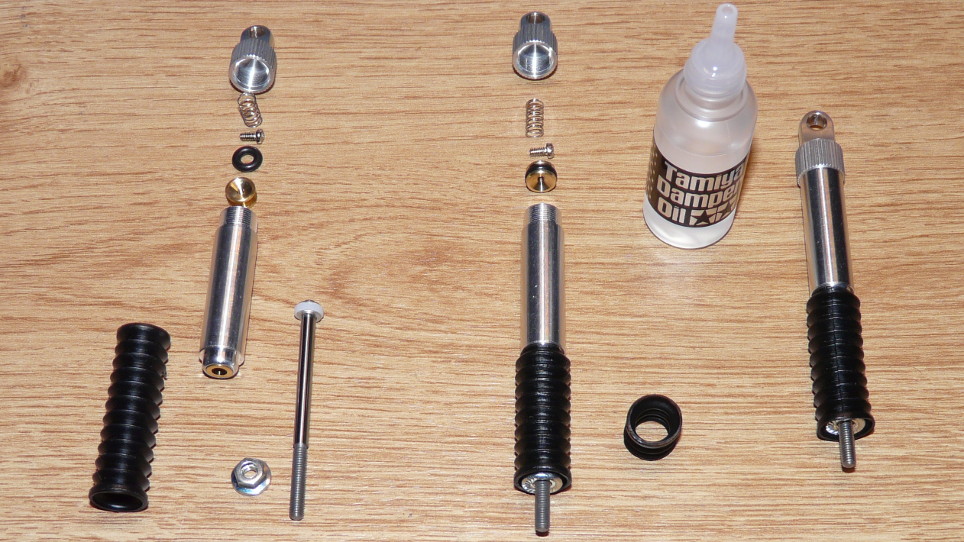
As you can see, these dampers do not use the current system with constant volume. And yet, Tamiya could have technically upgraded them into more modern units as they did with the re-released Wild One (therefore the previous comparison with the original version dampers ). This means Tamiya made their choice to remain faithful to the original 3 Speed.
You can also note this characteristic: these dampers have no external spring, meaning they do not provide any pre-load other than what offers the oil viscosity (#900, one of the thickest from Tamiya). In other words, this means absolutely no pre-load given the weight of the truck (already at this stage of the assembly). The piston rod rubber boots don't serve at all for suspension either: they are only meant to protect the piston rod from dust and dirt that could alter the damper work.
The wheel hubs
New step in the assembly:
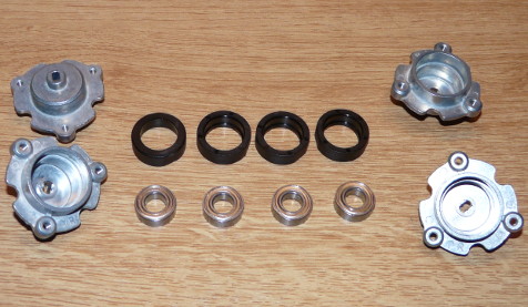
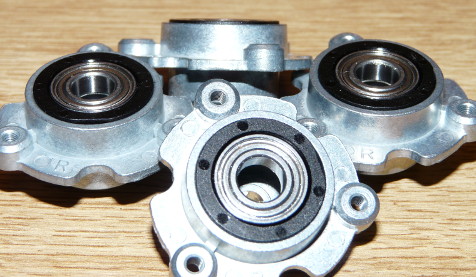
It is extremely important to properly insert the hard plastic ring maintaining the ball bearing right down into the wheel hub as shown on the second photo. If the ring is not inserted deep down into the hub, the wheel is unbalanced making it wobble at speed and look bent. Do not hesitate to force hard on the ring to properly insert it into the hub, and place the ball bearing afterwards (so it won't be damaged by the efforts applied on the ring).
One more important detail about these wheel hubs: as you can see on the second photo, they all wear the letter “R” engraved on their inner side. As in Right and Left, so you would expect “L” engraved parts too. As it seems, the distinction used to be important on the original editions, but it is not anymore with the re-released versions, probably due to minor alterations made by Tamiya in the meantime.
Finally, we can assemble the wheel hubs on the axles:
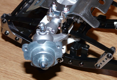
Again, 3 hours were needed to complete steps 11 to 17: building the Tamiya 3 Speed chassis is more challenging than most other models in the line-up, but also much more time consuming. That is fine as these are great moments... and it is not over yet .
This is a chassis overview at this moment of the build, after adding a skid plate under the front axle:
Next, we will focus a little bit on the Mountain Rider wheels.