")
Assembling the F201 chassis
I save you the before/after cleaning photos: my model wasn't dirty, but some cleaning can't hurt. As usual, the old school manner: bath of hot water + washing liquid and toothbrushing for plastic parts, bath of WD40 for metal parts.
So, let's go for the assembly, starting with the first step in the manual: building the front and rear ball differentials and then the dampers bellcranks.
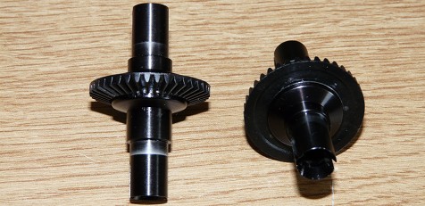
Sorry, I forgot to shoot photos when building the differentials: front and rear are the same and here they are once built (they are not the most interesting parts anyway). Next step is the dampers bellcranks assembly onto the front and rear differential housings. The step screws are to be fitted from the inside of the housings (thus their small head), the step nuts serving as rotation axles for the dampers bellcranks.
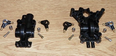
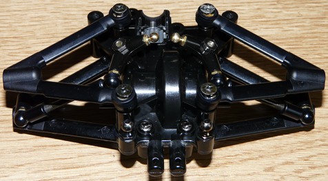
Next, end of the built for the front and rear gearboxes:
Front gearbox with its differential and propeller joint
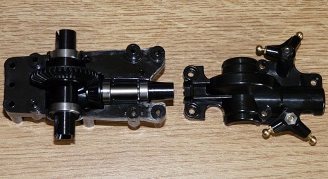
Rear gearbox with its differential and propeller joint
Built front and rear gearboxes
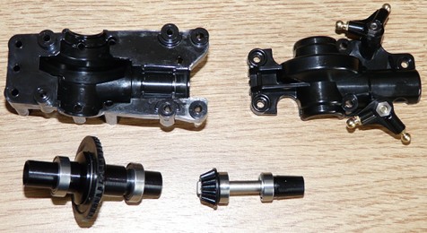
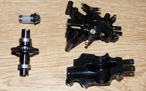
Then comes this moment when something becomes obvious: every single part in this chassis was designed to save space. Furthermore, several parts shapes are pretty tortured, like the two-part gearbox housings prove. In addition, there are pretty uncommon steps during the building process, like the arms for example:
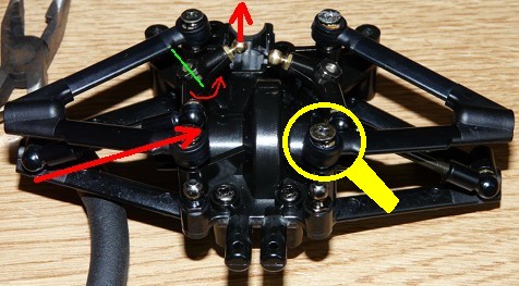
This is the rear gearbox: apart from the damper bellcrank movement you can see when comparing the two photos, focus on the "push rod" since it is quite interesting. Indeed, this specific part drives the arms movements up to the dampers using the bellcrank as a relay and amplifier (the bellcrank rotation axle is drawn with the green line). Moreover, these push rods also serve to adjust the rear drivetrain ride height. Just for your information, these push rods need their length to be precisely set at 18.5mm in between the joints. Most of the other tie-rods in the kit will require such precise measurements.
Another point of interest: the arms are mounted onto ball nuts (in the white magnifying glass). Here, the usual way of fixing arms to the chassis with an axle can not be used because of the gearbox housings shapes, forcing Tamiya designers to find an alternative solution.
Zoom on the arms ball nuts
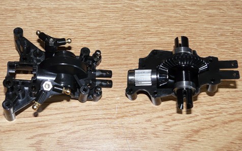
Front stabilizer plate
The front gearbox has a specific feature: a stabilizer plate that serves as the more usual anti-roll bar. Due to the F201 chassis layout, the usual anti-roll bar design couldn't fit, thus the use of this fiber plate bolted under the chassis. It is bolted to the lower arms sandwiching o-rings, allowing to setup its flexibility by tightening the screws. This stabilizer plate serves to reduce oversteer on high-grip surfaces.
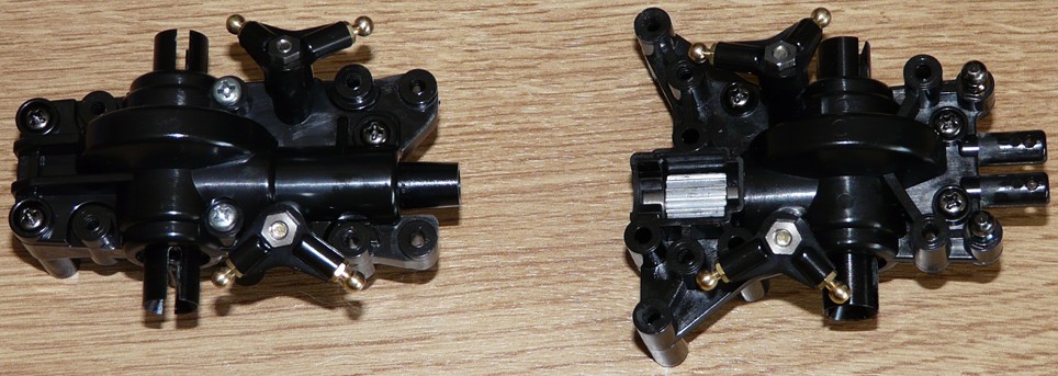
End of the rear gearbox built with uprights and drive shafts:
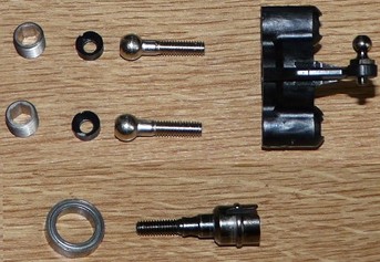
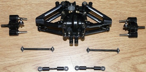
The assembly process is rather complex: the ball connectors are used to fix the uprights onto the arms. The plastic spacers are specific since they are flat on one side and concave on the other side to fit the ball connector head (concave means round-shaped on the inside). The adjusting nuts serve to place the ball connector screws inside their upright housing by pushing the concave plastic spacers. In practice, the adjusting nuts are meant to maintain the ball connector screw head into the upright housing, but allowing them free movement (no play though). See the ball connector screws position on the 3rd photo: they are free to move.
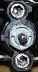
The above center photo was shot facing a built upright: at the center, the wheel axle and its aluminum hex (Hop-up 53056). Above and below the hex, the upright fixation points onto the arms: you can see the edge of the adjusting nut and at the inner bottom, the head of the ball connector screw featuring an hex (or Allen) socket for screwing them to the arm.
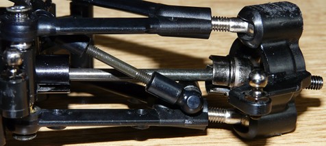
The first photo depicts a front upright being assembled. But there's more: every possible setup of the front drivetrain can be seen on this photo.
- oversteer / understeer: at the bottom left, you can see the fixing holes for the stabilizer plate on the lower arm.
- ride height: diagonally towards the lower arm end, the push rod linked to the damper bellcrank.
- camber: adjusted thanks to the ball connector screws fixing the upright to the lower and upper arms.
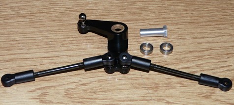
- toe-in / toe-out: adjusted with the steering rods (not visible here). Tie rods are used for this on the rear drivetrain.
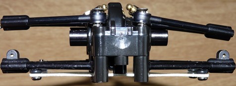
Since we are talking about steering, the system depicted on the second photo is made of two tie rods linked to the uprights, a pivot and a bellcrank. Despite the entire chassis being supplied with ball bearings, Tamiya oddly chose to use metal bearings for the steering system. Strange decision since the additional cost would be a futile argument. On principle, I replaced them with type 850 ball bearings, even if I couldn't spot any difference in this precise circumstance.
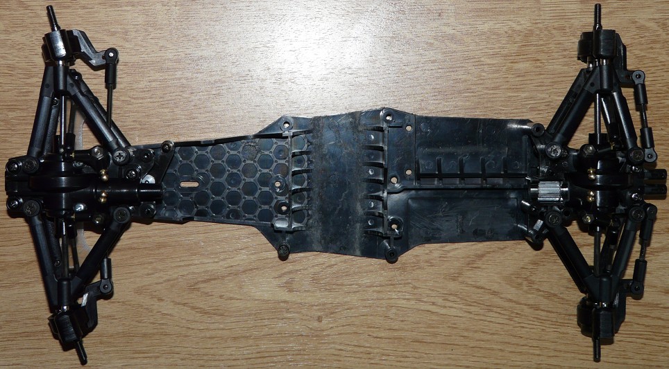
This is what we've done so far: